
Component Mastery: Exploring Electronic Elements
January 11, 2026- #course
- #skillet
- #electronics
https://skillet.academy/courses/enrolled/2624407
Resistors
Resistors are passive electronic components that limit or control the flow of electronic current in a circuit
- They dissipate electrical energy in the form of heat while reducing the voltage and current in a circuit
- types
- Fixed resistors (with a specific resistance value)
- variable resistors: such as potentiometers and rheostats, which allow for adjustable resistors
- variable
- Also known as potentiometers or rheostats, are electronic components whose resistance can be manually adjusted
- provide variable resistance in a circuit, allowing users to control the current flow or voltage levels
- potentiometers: used for volume control in audio equipment, tuning in radio and adjusting brightness in lighting circuits
- LDR (light dependent resistor): used to deterine brightness
- Rheostats: tuned once and never touched
- Trimmers: preset potentiometers, compact and precise
- Use Ohms law to determine the resistors needed in a circuit
Capacitors
Capacitors are electronic components that store and release electrical energy in a circuit
- They consist of two conductive plates separated by an insulating material (dielectric), storing energy in the form of an electric field when voltage is applied
- Applications
- Energy storage: temporarily store energy for power supply stabilization
- Filtering: smooth out fluctuations in power supply voltages
- Timing circuits: control timing elements in ossillators and timers
- Types
- ceramic: various forms
- electrolitic: high capacitor, power supply filtering, polarized
- tantalome: aerospace and military
- film: audio/video
- super/ultra: high capacity
$$E = \frac{1}{2} \times C \times V^2$$
- E is in Joules
- C is in Farad (F)
- V is Volts
Inductors
Inductors are passive electronic components that store energy in a magnetic field when electrical current flows through them.
- Composed of a coil of wire, inductors resist changes in current and can temporarily store energy in the magnetic field created by the current.
- Core is made of air, iron, and other ferite materials
- The number of turns in the coil, the coils geometry, and the coil material significanlty affects the inductuce.
- Measured in henries (H)
- When an electric current flows through the coil of an inductor it creates a magnetic field around the core, the energy is stored in the magnetic field
- Applications
- Filtering: used in power supplies to filter out AC noise from DC signals
- Energy storage: sotre energy in switch-mode power supplies
- Tuning circuits: employed in Radio Frequency (RF) tuning and signal processing to select specific frequencies
- Also used in transformers
- Chokes: block high frequency AC signals, allow low freq AC and DC to pass
- Metal detectors
- Can create fields that intefere
Calculate Inductance
$$L = \frac{N^2 \times μ \times A}{l}$$
- L is inductance
- N number of turns in the coil
- μ is the permeability of the core
- A is the cross sectional area of the core
- l is the length
Calculate Amount of Energy Stored
$$E = \frac{1}{2} \times L \times I^2$$
- E is energy in joules (J)
- L inductance in henries (H)
- I is current in amps (A)
Formula given by Faraday's law of induction
$$V = -L \times \frac{dI}{dt}$$
- V is induced voltage
- L is inductance
- dI / dt is rate of change of current over time
Self inductance
Property to induce a voltage in itself due to a change in current through the coil, also known as back EMF.
Mutual inductance
The magnetic field of one placed next to another that the magnetic field of one induces a voltage in another. Used in transformers where energy is transferred between a shared magnetic field.
Core Materials
- air: where core losses must be minimized. Low inductance, ideal for RF
- iron: higher. Power applications.
- Ferad core: high permiabillity and low losses at high frequency. Broader and switching power supplies. Capacitors for current.
Transformers
Transformers are electrical devices that transfer energy between two or more circuits through electromagnetic induction
- Composd of primary and secondary coils wound around a magnetic core, transformers step up (increase) or step down (decrease) voltage levels while maintaining the same frequency
- When a AC current flows through a primary winding it creates a time varied magnetic field in the core. This change induces a voltage in the secondary winding.
- Types
- step up, increase voltage
- step down, decrease voltage
- isolation, electrical isolation between primary and secondary
- auto transformer
- Applications
- Power distribution: step up voltage for long-distance transmission and step down voltage for safe residential and commerical use
- isolation: provide electrical isolation between different parts of a circuit to enhance safety
- impedance matchimng: match impedance between different circuits to maximize power transfer and miniize signal
- When exceding limitations of inductors, look at transformers
$$\frac{VS}{VP} = \frac{NS}{NP} $$
- VS seondary voltage
- VP primary voltage
- NS number of turns in secondary
- NP number of turns in primary
Diodes
Diodes are semiconductor devices that allow current to flow in one direction only, acting as one-way value for electical current
- comprised of a p-n junction, diodes conduct electricity when forward-biased (positive voltage applied to the anode) and block current when reverse-based (negative voltage applied to the anode)
- usually around 0.7 volts allows current to flow
- reverse increases depletion region
- forward dcecrease depletion region
- forward: current increases exponentially
- reverse: stays near 0 until breakdown voltage is reached, then conducts in reverse
- Applications
- Rectification: convert AC to DC in power supplies
- protection: protect circuits from voltage spikes by clamping and redirecting excess voltage
- signal demodulation: extract audio signals from modulated radio frequency signals in communication devices
- types
- standard: rectification, clamping, general purpose. Variability to block reverse current
- sender: allow reverse to flow once break down voltage is reached
- shotkey: low forward volage drop (0.2, 0.3), high frequency. Power supplies, RF cicuits
- Varactor: variable capitors, controlled by reverse bias voltage. Tuning, radio frequency
LEDs
Light Emitting Diode: are semiconductor devices that emit light when current flows through them, converting electrical energy into visible light.
- Operation: emit light when forward-based (positive voltage applied to the anode)
- Types: available in various colors (red, green, blue, white) based on semiconductor materials and construction
- Energy band gap of material
- Red, orange, yellow: Gallium arsenide phosphide (GaAsP) or Gallium phosphide (GaP). Lower band gap
- Green: gallium phosphide (GaP) or Gallium nitride (GaN) higher band gap
- Blue: Gallium nitride (GaN) or Indium gallium nitride (InGaN). higher energy band gap. Harder to make. Paved the way for white LEDs.
- Threshold voltage, typically 1.8v - 3.3v depending on color and material. Below its off. As it gets passed, higher voltage is brighter.
- Use resistors to prevent damage
- One lead is longer than the other to show anode vs. cathode
- Applications
- Used in eelctronic devices to indicate power status, operation modes, and alerts.
- Lighting: effecicent alternative to incadescent bulbs in displays, singage, automotive lighting and general illumintation
- Displays: Integrated into alphanumeric displays and large-scale vidceo screens (LED TVs)
Rectifiers
Rectifiers are electronic devices that convert alternating current (AC) to direct current (DC), essential for providing stable DC power from an AC source
- Utilizes diodes to allow current to flow in only one direction, effectively transforming the AC input into a pulsating DC output.
- Half wave: only half the signal goes through, creates a pulsating DC output. Inefficient, using half the AC
- Full wave
- center tap transformer with two diodes, splits the signal into two haves. Doubles the output
- bridge rectifier, 4 diodes in a bridge configuration, more efficient and common. Converts both positive and negative halves to DC
- has ripples, pulsating, use filtering to smooth
- Applications
- Power supplies: used in AC-DC power adapters and battery chargers to provide DC voltage
- Signal demodulation: extracts the DC component from AC signals in radio receivers
- Voltage multiplication: in voltage multiplier circuits to generate high DC voltages from lower AC voltages
Transistors
Transistors are semiconductor devices used to amplify or switch elctronic signals and electrical power
- Consist of three layers of semiconductor material, forming either an NPN or PNP structure, with three terminals: emitter, base and collector. By applyi8ng a small current to the base, a larger current flows from collector to the emitter (or vice versa for PNP)
- BJT are very common.
- FET use an electric field, more energy efficient
- Applications
- Amplification: increase the strength of weak signals in audio, radio, and other communication devices
- Switching: act as electronic switches in digital circuits, controlling current flow in computer processors and memory
- Regulation: Used in voltage regulators to maintain a constant output voltage
- bi-polar junction (BJT), analog and digital circuits. Amplications and switching
- field effect (FET), electrical fields. N-channel and P-channel. More energy efficient
- darlington: two BJT for high current gains.
Integrated Circuits
Integrated Circuits (ICs) are compact, sendiconductor devices that contain multiple electronic components (transitors, diodes, resistors, capacitors) on a single chip to perform various functions.
- ICs integrate various circuite elements into a tiny package, enabling comnplex functions like amplication, signal processing, and digital computation. They can be analog, digital, or mixed signal.
- Also called micro controllers
- Applications
- Computers and mobile devices. Serve as microprocessors, memory chips, and logic gates, forming the backgone of digital technology
- Consumer electronics: power devices like televisions, radios, and home appliances by providing control and processing signal capabilities
- Automotive and industrial: used in control systems, sensors, and communication modules to enhance functionality and performance
Sensors
Sensors are devices that detect and respond to changes in environmental conditions, converting physcial phenomena into electrical signals.
- Operate by sensing physical inputs such as light, temperature, pressure, motion, or chemical properties and output an electrical signal that can be measured and processed. Often using Variable resistors.
- temperature sensors: termisiters, thermocouples
- light sensors: photo diodes, light meters, optical communication, automatic lighting, LDR
- motion sensors: accelerometers, smart phone, vehicle stability
- gyroscope: measure rate of rotation, gaming, smart phones, and drones
- chemical sensors: detect alcohol in blood
- bio sensors: detect biological anolites, glucose sensor
- pressure: meassure force, weather, industrial process control, pizoelectric and capacitive
- infrared: thermal imaging, remote controls, proximity
- ultrasonic: high frequency sounds waves, measure distance, parking, robots, level measurements
Actuators
Actuators are devices that convert electridcal energy into mechanical motion, enabling control and movement in various systems
- Operate by receiving a control signal and producing a physical change, such as linear motion, to perform a specific task.
- Input energy to mechanical energy. Electrical, pneumatic, or hydrolic
- Motion: linear or rotary
- Many have feedback to capture position, speed, or force of the motion, allowing precise control
- Electric motors, converts electrical energy to rotational movement
- Solonoids: produce linear energy by converting energy to an electro-magnetic field moving the plunger or core. Used in locking mechanisms, automotive starters, fuel injectors, and transmission controls. Industrial applications, precise control of a bolt.
- pneumatic: compressed air to generate motion. Automation like pick and place, packaging systems. Robotics to mimic muscle tissue.
- DC motors: brush or brushless. Brushless are more reliable. More types.
- Examples
- Elecrtric motors: used in robotics, household appliances, and industrial machinery to create rotation movement.
- Solenoids: employed in locking mechanisms, such as electronic door locks and automotive start systems, to provide linear motion.
- Pneumatic actuators: utilized in automation systems and machinery, using compressed air to generate mechanical motion for tasks like clamping or moving parts
Circuit Design
- Define the purpose: clearly outline the circuits function and what components are necessary to achieve it.
- Chose components: select components such as resistors, capacitors, diodes, transitors, and integrated circuits baszed on their electrical characteristics and suitability for the application
- Learn to read data sheets
- Circuit schematic: Draw a schematic diagram illustrating how components are connected, showing the flow of current and signal paths
- Calculate values: calculate resistor values for current limiting, voltage dividers, or impedance matching using Ohm's law and component data sheets
- Prototype and test: build a prototype on a breadboard to verify functionality and performance. Test the expected behavior, voltage levels, signal integrity, and any necessary adjustments
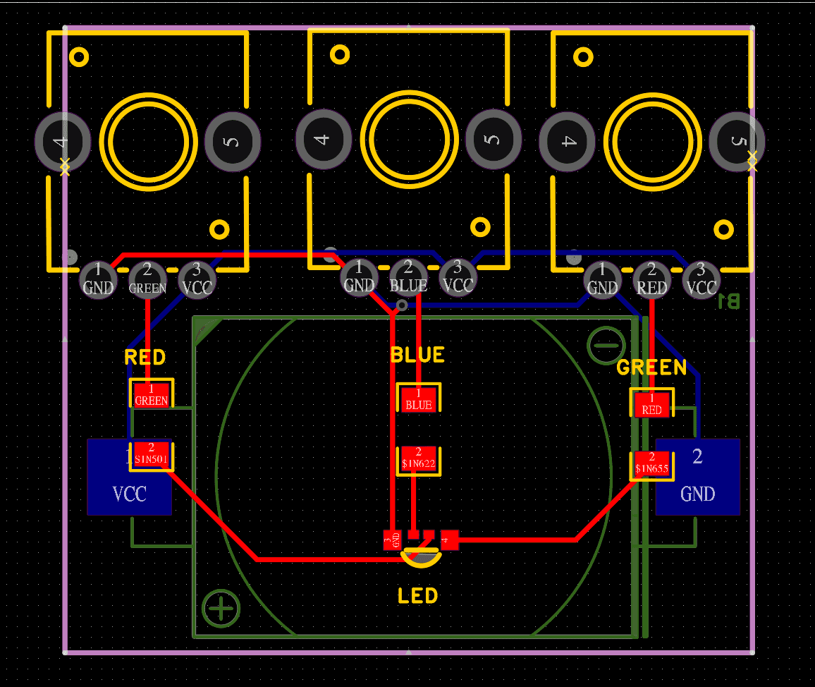
- PCB Design (optional): For more permenant solutions, design a printed circuit board (PCB) layout using CAD software to minimize size, optimize routing, and ensure electrical connections are correct.
- Documentation: document the circuit design, including schematics, component values, and any special notes for future reference or replication
- Iteration and optimization: iterate on the design based on testing results and feedback, optimizing for performance, efficiency, and reliability
Analog vs. Digital
Analog
- Utilize continous signals that vary in amplitude to represent information
- Output is smooth and continous waveform
- Examples: audio amplifiers, analog sensors, analog-to-digital converters
Digital
- Use descrete signals that represent information in binary form (0s and 1s)
- Output is discrete and characterized by high or low voltage levels
- Examples: microprocessors, memory chips, logic gates
Comparing
- Signal representation: analog circuites represent data with varying voltages, while digital circuits use binary states (on/off)
- digital stores data reliably even with noise
- Complexity: digital circuits can handle complex operations and calculations, whereas analog circuits are typically simpler in design
_ Noise sensitivity: analog circuits are more susceptible to noise and interference compared to digital circuits, which are most robust.
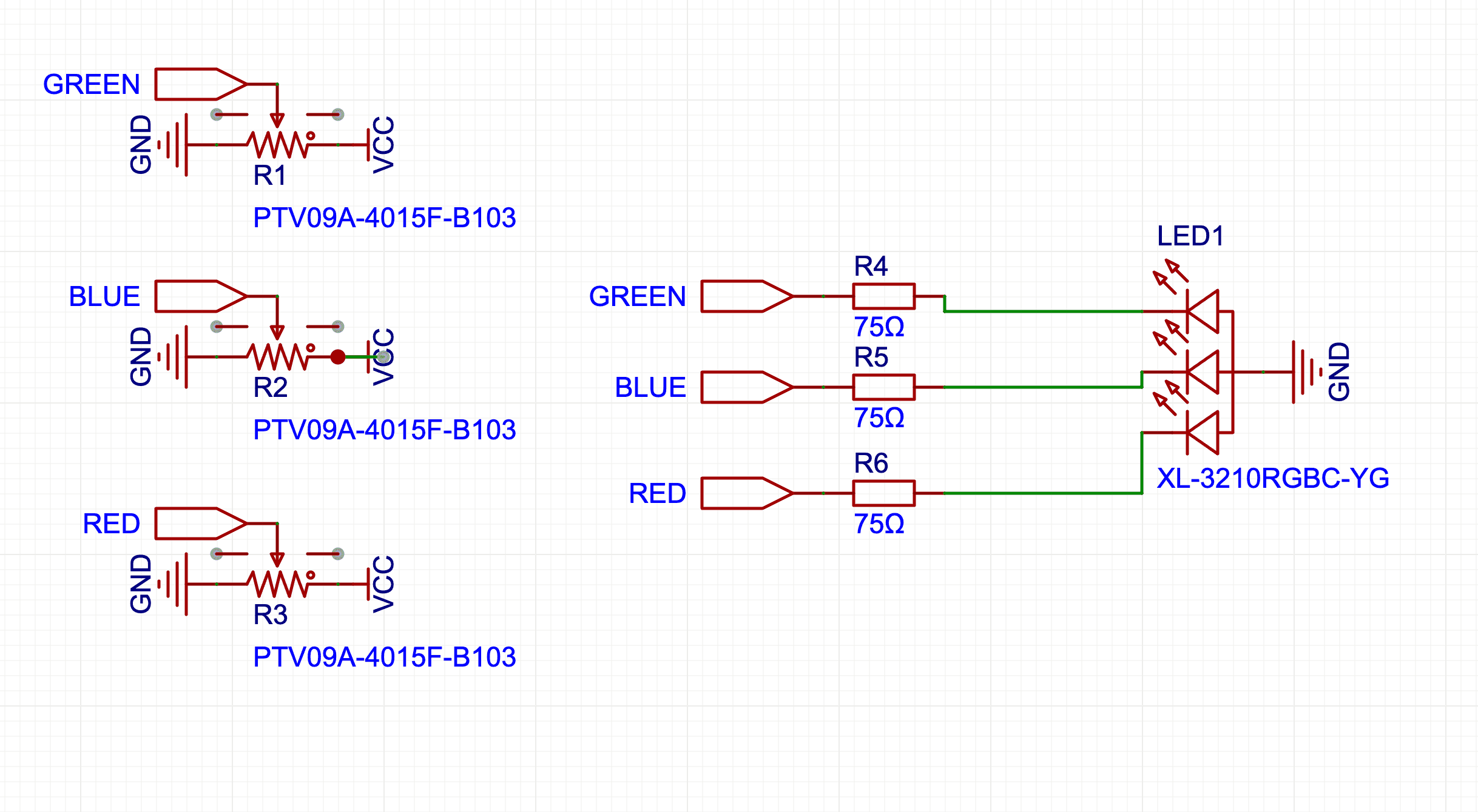
Circuit Symbols
Circuit schematics are visual representations of electronic circuits using symbols to denote components and lines to show connections
- Provide a clear, standardized way to understand and design circuits without needing to physically build them
- Engineers asnd designers use schematics to plan, analyzxe, and communicate circuit designs efficiently before actual construction, ensuring functionality and reliability
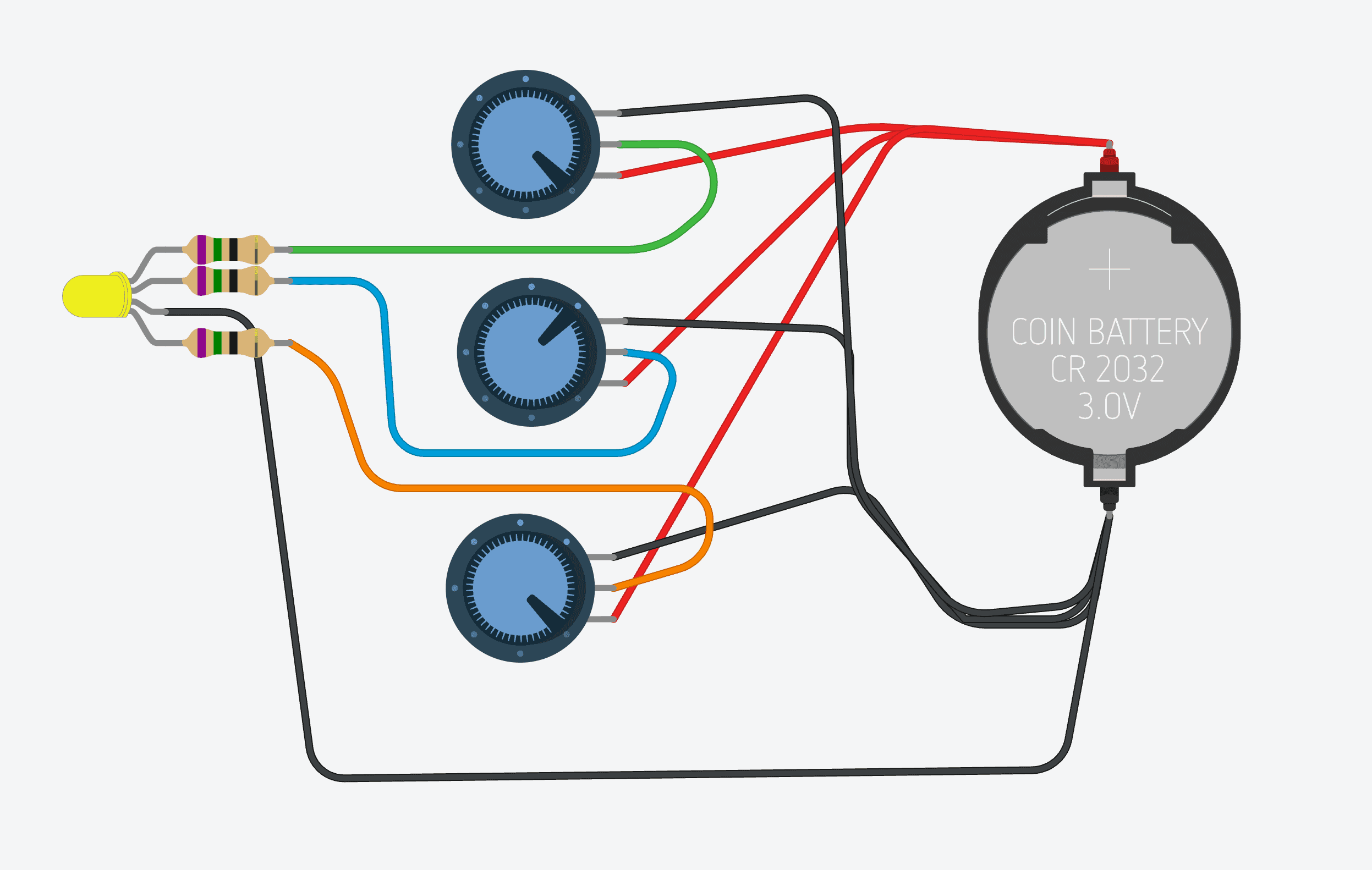
Simulating Circuits
- https://www.tinkercad.com/: online autocad tool
- Can export image or .brd file
Desiging and Manufacturing Circuits
- https://easyeda.com/page/download?src=index
- JLCPCB is very large, manufactured in china